How to Flash the Arduino Bootloader to a Custom nRF52832 Design
Jun, 03 2024
I've been working with a custom nRF52832 board design and I wanted to program the device with some demo software. The production board runs Zephyr RTOS, but I wanted a quick and dirty prototyping environment so I turned to Arduino.
Note that you will need a J-Link programmer of some sort to program the bootloader. You can use the nRF52832 Development Kit, a J-Link EDU Mini (for hobby projects) or a full fledged J-Link programmer (for commercial projects).
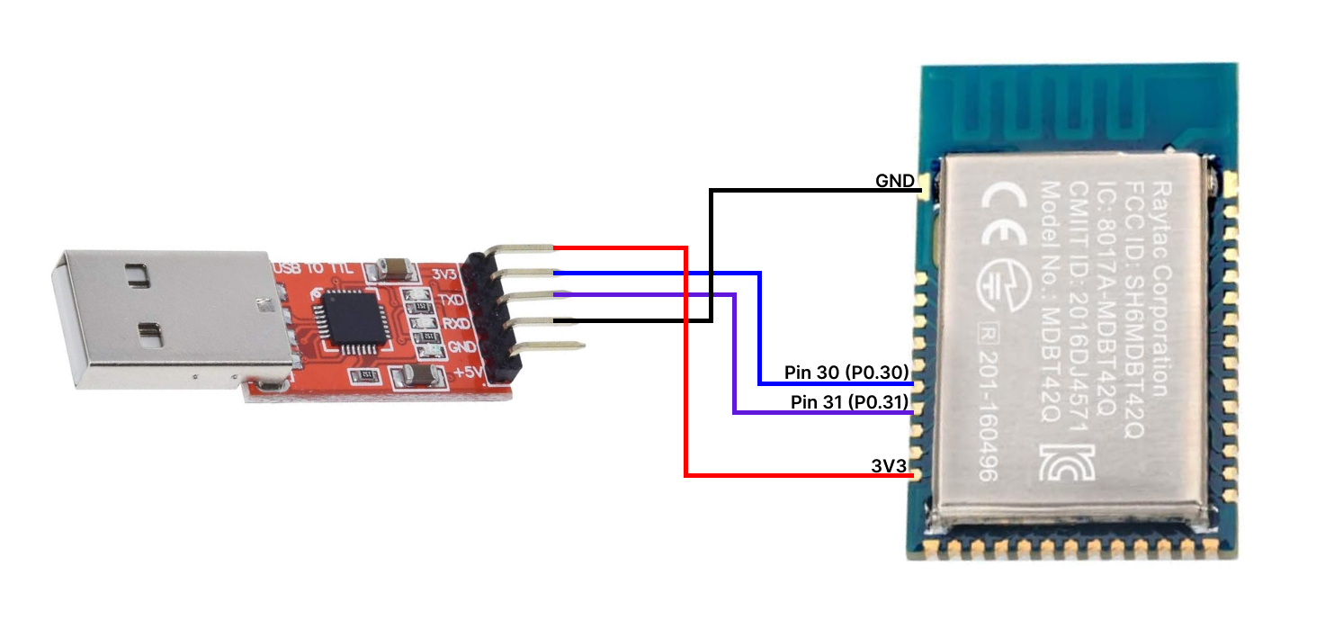
You will also need a UART to USB converter such as this one. This will be used to flash your nRF52832 in the Arduino IDE after the bootloader is installed.
I'll be using a BLE module with some example connections for this guide, but you can adapt these steps to your design.
Moving forward, let's assume your design exposes P0.30 and P0.31 pins as the UART RX and UART TX pins as shown below:
Configure the bootloader
You'll need to clone the Adafruit_nRF52_Bootloader repository to your computer. You can see the bootloader's list of supported boards in the src > boards directory of the repository.
We'll modify the feather_nrf52832's bootloader configuration because it most closely matches our end goal.
Navigate to src > boards > feather_nrf52832 > board.h. Notice the different sections for LED, BUTTON, and UART. We need to update these sections to match our PCB design.
Starting with the UART configuration, update the pins to match your design. P0.31 = TX and P0.30 = RX in our case. You can ignore the CTS and RTS pin definitions as we are not using hardware flow control.
Remember that RX from the converter should be connected to TX on the microcontroller and TX from the converter should be connected to RX on the microcontroller.
/*------------------------------------------------------------------*/
/* UART (only used by nRF52832)
 *------------------------------------------------------------------*/
#define RX_PIN_NUMBER      30
#define TX_PIN_NUMBER      31
#define CTS_PIN_NUMBER     0
#define RTS_PIN_NUMBER     0
#define HWFC               false
Next we can look at the LED section. This is only for designs with onboard indicator LEDs. The LED you specify here will indicate that your device is in bootloader mode and is ready to be flashed by the Arduino IDE. My design does not have an onboard LED, so I am assigning LED_PRIMARY_PIN to a random GPIO pin.
/*------------------------------------------------------------------*/
/* LED
 *------------------------------------------------------------------*/
#define LEDS_NUMBER        1
#define LED_PRIMARY_PIN    17
#define LED_STATE_ON       1
Finally, we have the button section.
BUTTON_1 is used as the DFU button. This will force the nRF52 into bootloader mode if it is pressed during a power cycle or a reset.
BUTTON_2 is used as the FRST button. This will perform a factory reset, erasing any Arduino code previously loaded if it is pressed during a reset.
You can read more about the DFU and FRST buttons here.
My design will not use any buttons. Instead I'll rely on my device pausing in bootloader mode for a short period before loading the Arduino code. We'll talk more about this.
Once again, I am assigning 2 random pins for the buttons section.
However, if you have these pins connected to GND (active low) at start up, this might cause problems exiting the bootloader as it might think a button is being pressed.
Note that if 2 buttons are not defined, you might run into build errors.
/*------------------------------------------------------------------*/
/* BUTTON
 *------------------------------------------------------------------*/
#define BUTTONS_NUMBER     2
#define BUTTON_1           23
#define BUTTON_2           24
#define BUTTON_PULL        NRF_GPIO_PIN_PULLUP
Since I am not using any buttons in my design, I decided to modify the bootloader period to make it easier to upload code. By default the bootloader will pause for 1 second after a reset to wait for any new code coming from the Arduino IDE.
I decided to prolong this wait period so it is easier to time my resets with uploading new code. This is strictly optional but recommended if you are going without a DFU button.
You can increase this delay by modifying DFU_SERIAL_STARTUP_INTERVAL in src > main.c
#define DFU_SERIAL_STARTUP_INTERVAL 20000 // ms
As you can see above, my custom bootloader will pause for 20 seconds after a reset, waiting for new Arduino code before loading any Arduino sketches.
Building the Arduino bootloader for your nRF52 design
First, make sure you have the ARM GCC toolchain installed on your computer.
Choose the latest release and download the installer necessary for your operating system. Take note of the installation path for if you run into issues later. Also, make sure to "Add to PATH" if prompted.
Open a new terminal window inside of your local copy of the Adafruit UF2 Bootloader.
Run the following command to initialize the submodules:
git submodule update --init
Next, create and activate a virtual python environment by running:
python3 -m venv myenv
source myenv/bin/activate
Install the python dependencies required for the build system:
pip3 install intelhex
pip3 install adafruit-nrfutil
Now run the make command to build the bootloader:
make BOARD=feather_nrf52832 all
Notice the new _build folder that this command creates. It is a good idea to delete this folder each time you make changes to the bootloader configuration to make sure everything gets rebuilt.
Connect the following pins from your JLINK programmer to your nRF52832 module:
- SWDIO
- SWCLK
- 3V3
- GND
Then run the flash command:
make flash
You should now be able to program your board with the Arduino IDE and your UART to Serial converter! You should select the nRF52832 Feather board option and your UART to Serial converter as your port option.
(Make sure you have the nRF52's board support package installed as described here)
If you have a DFU button: press and hold it, then reset (or power cycle) your module then release the DFU button to enter bootloader mode.
Otherwise if you are relying on the DFU_SERIAL_STARTUP_INTERVAL as I am, make sure to reset your board just before the Arduino IDE tries to upload your sketch.
One thing to note: you may have to set your UART pins before the Serial.begin call if you want to get Serial output on your custom board. For this example it would look like this:
Serial.setPins(30, 31);
Serial.begin(115200);